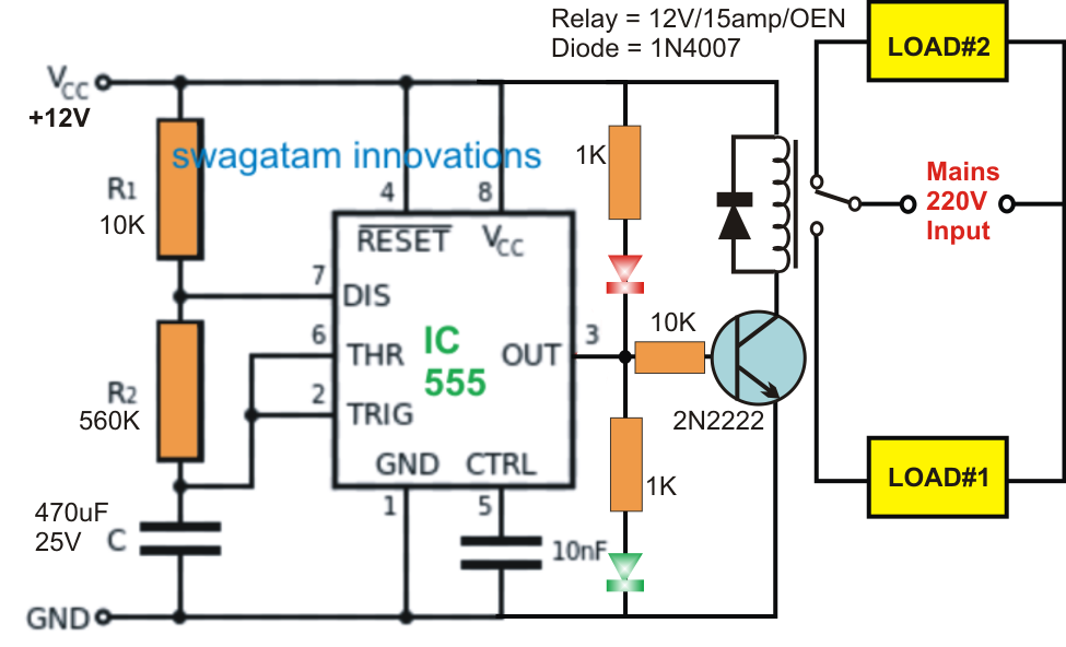
Ic 555 Timer Circuit Diagram
Timer ic 555 tester 555 timer diagram internal ic astable circuit multivibrator monostable bistable circuitspedia 555 timer tester ne555 engineeering
GO LOOK IMPORTANTBOOK: IC 555 and CD 4047 measuring electronics
Introduction to the 555 timer Alternate switching relay timer circuit Timer graham lambert
Timer 555 circuit relay led ic circuits switching projects off homemade alternate two alternating electronic astable simple 220v mains board
555 ic timer diagram circuit astable description pinout pins block using multivibrator ic555 internal circuits ground structure explain figure its555 timer ic pin diagram features and applications How does ne555 timer circuit works555 timer diagram ic block circuit ne555 controller configuration op working pins flip flop pwm discharge electrical resistive.
Timer 555 circuit diagram schematic ne555 datasheet pinout discrete kit does block circuits transistor works eleccircuit integrated connection functional pinsIc astable multivibrator Astable multivibrator using 555 timerGo look importantbook: ic 555 and cd 4047 measuring electronics.

555 timer ic-block diagram-working-pin out configuration-data sheet
.
.


Alternate Switching Relay Timer Circuit

How does NE555 timer circuit works | Datasheet | Pinout | ElecCircuit.com

GO LOOK IMPORTANTBOOK: IC 555 and CD 4047 measuring electronics

Introduction to the 555 Timer - Circuit Basics

Astable Multivibrator using 555 Timer

timer ic 555 tester | Best Engineering Projects